How do you manage dependencies in your project? Since an image speaks a thousand words, I’ve always been a fan of visual management. Unfortunately, Visual Studio Professional doesn’t provide a way to do this. In the Premium and Enterprise editions you can visualize code dependencies on dependency graphs. But I don’t think this is enough. An architectural diagram with every assembly or namespace in my solution doesn’t tell me that much. It contains too much information.
Fortunately, there is a tool that can help you manage dependencies in the .Net world: NDepend (there is also a Java port – JArchitect). NDepend is a static analysis tool that, among other things, allows you to visualize dependencies. After I first ran NDepend on a project, I was overwhelmed with information. Then I took some time to play around and discover what can it tell me about my solution. NDepend integrates into Visual Studio quite nicely and points you in the right direction through tool tips and links. This is useful for people who prefer learning by doing. Aside from giving you information, it also tells you what to do with that information.
NDepend has two main views for managing dependencies: the Dependency Graph and the Dependency Structure Matrix. Apart from these, there is also an Abstractness vs Instability report that can be helpful. In this blog post, we’ll discuss some of the things that these views can tell you about your solution.
Dependency Graph
You’re probably used to Dependency Graphs. In this graph, the nodes represent elements (assemblies/namespaces/types/members) and the edges represent dependencies. This view is useful when there is a limited number of nodes. When the graph gets too big, this view gets unmanageable.
Viewing the internal structure of an element
You can view the internal structure of a class/namespace/assembly by clicking the View Internal Dependencies on Graph. Here is the structure of a class:
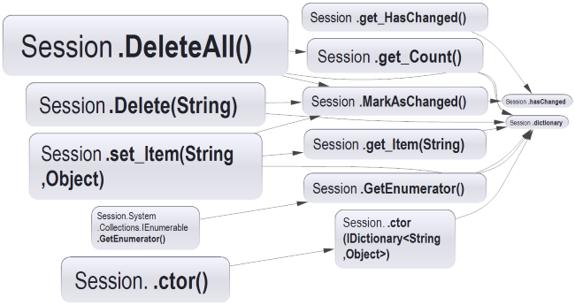
I find this useful for discovering parts of the code you don’t know. For small enough classes you can use the graph view to analyse cohesiveness. Just by looking at the graph above and hovering over different elements you can notice that it’s cohesive. If you see two clusters of members, maybe it’s a good idea to extract a class. This can be a good entry point when you want to refactor a God Class, although it will probably look like this:
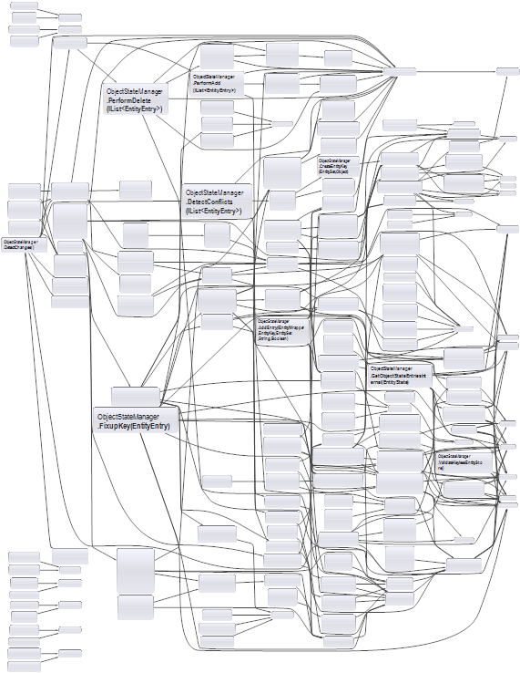
In this case, it’s probably best to use the dependency matrix, which we’ll discuss shortly.
For a given element, NDepend also allows you to see inbound dependencies, outbound dependencies or, for a class, its inheritance tree. Again, this can provide useful insight for refactoring.
Removing a dependency
Here’s the Assembly Dependency Graph for NUnit:

Let’s say that, for some reason, you decided that mock-assembly shouldn’t reference the nunit.framework assembly. How would you break this dependency? You can see what codes needs to change if you select the edge and Build a Graph made of code elements involved in this dependency.
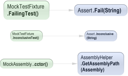
Now you know which method level dependencies you have to break! Think of how useful this is when you are trying to extract a class from a big ball of mud or when you’re reducing coupling in a legacy code base by introducing responsibility layers. This basically allows you to break down work into tasks.
Tip: You can also click on the edge and Generate a code rule that warns if this dependency exists. This ensures that people don’t accidentally introduce unwanted dependencies.
Dependency Structure Matrix
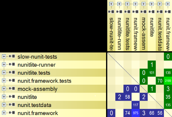
The problem with the Dependency Graph is that it doesn’t scale. As in the God Class example above, you wouldn’t know where to start. This is where the Dependency Structure Matrix (DSM) shines. This matrix contains the same elements in the rows and columns headers. If the element in row A depends on element in column B, then the corresponding cell will contain information about that dependency.
Logical Coupling
Before digging deeper into DSM use cases, we need to define the types of logical coupling:
- Afferent Coupling (Ca). Also known as Incoming Coupling – who depends on you
- Efferent Coupling (Ce). Also known as Outgoing Coupling – on who do you depend
This metrics are useful at multiple levels: assembly, namespace, class and even method. If you look on a row in the DSM, the blue cells are a measure of Ca and the green cells are a measure of Ce. For columns, it’s the opposite: the green cells are a measure of Ca and the blue cells are a measure of Ce.
Now that we have defined what Afferent and Efferent Coupling is, how do you calculate it? For a software package (namespace or assembly), Wikipedia says that you should count the number of types. But what about types? If type A uses 4 methods from type B, what should be the values of Ca and Ce?
- Ca=1, Ce=1
- Ca=4, Ce=4
- Ca=4, Ce=1
- Ca=1, Ce=4
There probably isn’t a definitive answer, so I would like to have the option to calculate it in different ways. The DSM has this flexibility. You can select the Weight on Cells to be:
- Direct & indirect depth of use
- Direct: # namespaces
- Direct: # types
- Direct: # members
- Direct: # methods
- Direct: # fields
Also, as you can see in the list above, you can even select indirect dependencies. This could give you a measure of the impact of a change and how it could cascade through the solution.
Looking for patterns
The DSM is useful because it makes patterns in your code base visible. And if patterns are visible, you can also notice when things go astray.
High Afferent Coupling
For example, let’s say you look at the dependencies between assemblies and you notice the following line with many blue cells (for a given row, blue cells indicate elements that depend on it):

Is this a bad thing? As usual, it depends. If this is framework type code, then you would expect it to be used in many places. This is because framework code should be stable. If you don’t change it, then you don’t have to worry about breaking its clients. In fact, it might be a warning sign if this type of code isn’t used that often.
For example, you would expect that a substitute framework (like NSubstitute or FakeItEasy) to be used in many of your unit test projects. If it isn’t, then some questions come to mind: Are people using other substitute frameworks? Are they hand coding their own stubs and mocks? Or maybe they aren’t using fakes at all (or testing will real collaborators). Again, this isn’t necessarily a problem. But when a certain type doesn’t fit the pattern, you should dig deeper.
What if a Dependency Injection framework has high Incoming Coupling? This is big warning sign. Only the composition root should reference it. If you have references to a DI framework scattered across the code base, you’re using it wrong. The DSM makes this problem visible.
Even if it’s not framework type code, the principle is the same: code with high incoming coupling should be stable. So another warning sign are concrete types with high Ca (we’ll also touch on this in the Abstractness vs. Instability section). The solution is simple: extract an interface so you depend on abstractions. But extracting an interface is just the first step. You should take the time to design the contract and think if the abstraction adheres to the Single Responsibility Principle. If it doesn’t, it’s better to split it into multiple interfaces. Applying the Interface Segregation Principle helps you keep the interfaces small and focused.
High Efferent Coupling
What if you see this column with many blue cells (for a given column, blue cells indicate the elements that it depends on)? Is this a bad thing?
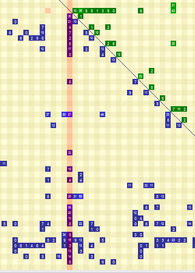
It depends. Most probably, it is a problem. Code with high Outgoing Coupling usually doesn’t do only one thing. But there are exceptions.
- The composition root knows about many types. That is its job: to construct the object graph.
- The presentation layer (or top layer) code might also fit in here. Usually, nobody depends on Controllers (as in the C in MVC), but they depend on many types (DTOs, View Models, Services, Mappers etc.)
Visualizing Layered Code
The DSM is good at detecting layered code. If you don’t have dependency cycles, then the matrix should be triangular: all blue cells in the lower left triangle and green cells in the upper right triangle. Code like this is easier to understand and reason about.
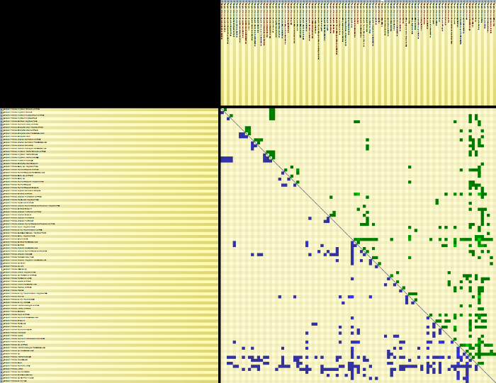
These are just a few examples of patterns that you can observe using the DSM. Every project is unique so you should think about the context when analyzing your own project. After I first ran NDepend on my project, I started looking for clusters of elements and elements that don’t fit in their surroundings. The DSM gives you a good overview of the main components if you’re looking at an assembly or namespace level. But you also have the option to zoom in and see dependencies for types and even members. It’s interesting how many things a matrix can tell you about your code base.
Detecting Dependency Cycles
In most of my projects I have used an assembly as a logical component. This led to a large number of projects and slower builds. Visual Studio works better with fewer larger assemblies than with many smaller ones. And, if you think about it, it makes sense, since an assembly is a physical unit. A better approach could be to use namespaces as logical components. This will reduce the number of assemblies. The problem is that, although Visual Studio can prevent introducing dependency cycles between projects, it can’t detect dependency cycles between namespaces. This makes it easy to introduce unwanted dependencies. Fortunately, these cycles are visible in NDepend’s DSM:
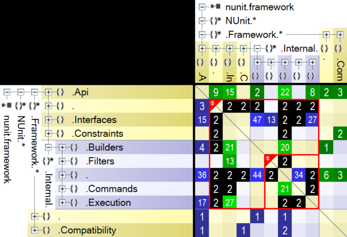
The black cells indicate namespaces that are mutually dependent. The red rectangles show all the elements that are part of a dependency cycle. So, if you treat namespaces as logical components, this matrix shows that you have a problem. Usually, even though two namespaces depend on each other, there is a parent-child relationship. This means that there are more dependencies in one direction than in the other. To remove the dependency, you can:
- apply the Dependency Inversion Principle. If type A (namespace NA) depends on type B (namespace NB) you can define an interface IB in namespace NA. A will now depend on IB and B will implement IB, so the dependency is from NB to NA.
- extract the common code in a separate assembly – C. Assemblies A and B should both depend on C.
If there is a large number of dependencies both ways, maybe the code is telling you that these two namespaces are one component. In this case, you could merge them.
Detecting Coupled Components
Let’s assume you’re sold on the idea to use namespaces as logical components. But your current solution has hundreds of projects. How do you go about merging assemblies? One idea would be to look at the current dependency structure and see what highly coupled components it detects.
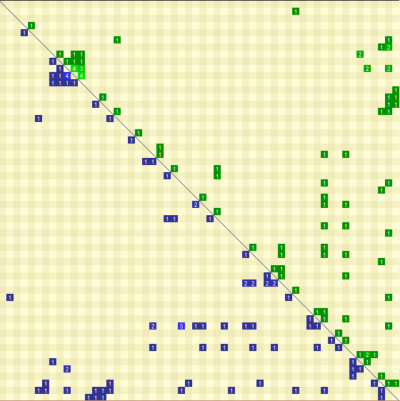
In the image above, the square in the upper left corner contains a tightly coupled component. You can investigate the dependencies between the assemblies and, if appropriate, merge them in a single assembly, with a namespace per existing assembly. Since there are no dependency cycles between assemblies, this will create a nicely layered component. This should create highly cohesive assemblies. This idea is not limited to assemblies. You can apply it to detect tightly coupled clusters of types or namespaces too.
Abstractness vs. Instability
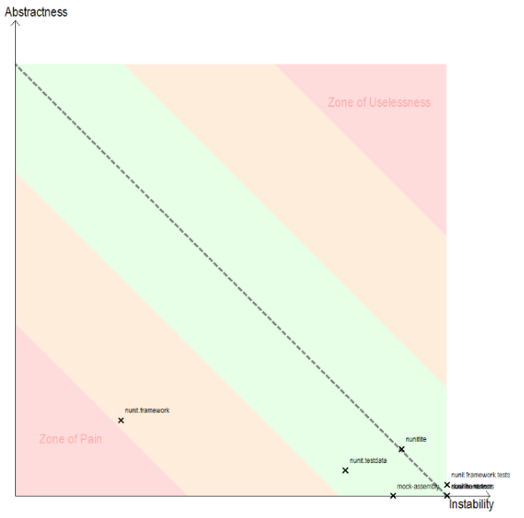
Another interesting view is Abstractness vs. Instability.
Uncle Bob defined these metrics in The Principles of OOD article series:
- I : Instability : (Ce ÷ (Ca+Ce)) : This metric has the range [0,1]. I=0 indicates a maximally stable package. I=1 indicates a maximally instable package. (As described above, Ce is Outgoing Coupling and Ca is Incoming Coupling)
- A : Abstractness : abstractClasses ÷ totalClasses
With this definitions, the instability metric tells us how easy is to change an assembly. A stable assembly is hard to change. This is because it has a large number of incoming dependencies. When you change it, you risk breaking its clients. What’s important is to balance abstractness and instability. First, let’s discuss what zones you want to avoid:
- The Zone of Pain contains assemblies that are stable and concrete. Since they are concrete, we will probably need to change their implementation. Because they are stable, the change can trigger a cascade of updates in dependent assemblies.
- The Zone of Uselessness contains assemblies that are instable and abstract.
Balancing abstractness and stability means that we want to be as close as possible to the Main Sequence. This contains the assemblies for which A + I = 1. The ideal positions are on the edges of the Main Sequence:
- In the top left corner we have assemblies that are completely stable and abstract. Since they are abstract, they don’t have many reasons to change. Since they’re stable, they shouldn’t change.
- In the bottom left corner we have assemblies that are completely instable and concrete. This means that nobody depends on them, so we can change them. And we will probably need to change them, since they depend on other, more stable packages. UI code usually falls in this category.
Conclusion
Although it might seem daunting at first, learning to read the data that NDepend gives you can help improve the quality of your product. Architects will find the high level view useful for detecting architectural inconsistencies. Developers will find it useful to understand code and get all the information needed to refactor it. I’ve just started using NDepend, but I already feel it’s helping me make more informed decisions.
If you want to find out more about NDepend and managing dependencies, check out these resources:
- NDepend documentation
- Practical NDepend Pluralsight course by Erik Dietrich (be sure to also check his blog)
- Hanselminutes Podcast 163 – Software Metrics with Patrick Smacchia
- Hanselminutes Podcast 51 – Static Code Analysis with NDepend
Pingback: Querying Your Code Base Using NDepend's CQLinq - Simple Oriented Architecture
Pingback: Visualizing Code Metrics with NDepend - Simple Oriented Architecture